
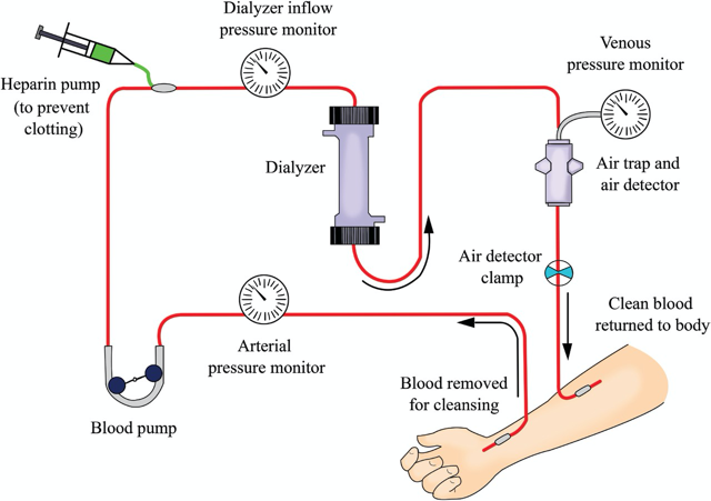
The blood circuit begins at the vascular access to pump the blood from vascular access to the dialyzer and blood is returned from the dialyzer back to vascular access.
The inflow (arterial) blood line connects the vascular access to the dialyzer, and the outflow (venous) blood line runs from the dialyzer back to the vascular access. The arterial segment is most often color-coded red; the venous segment is most often color-coded blue. Bloodlines are smooth on the inside to reduce clotting and air bubbles. The inner diameter of the blood tubing is small. Only a small amount—about 100–250 mL—of blood is outside the patient’s body at any time.
Each set of blood tubing has different, specialized parts. The order in which those parts are installed in the delivery system varies with the system’s design, prescribed treatment, and the monitoring desired.
The blood circuit consists of the following components:
Pressure monitors (arterial (pre-pump), pre-dialyzer, and venous)
Blood tubing
Blood pump
Heparin pump
Air Leak Detector and Clamps
 The Blood Circuit
1. Inflow Blood Line (Pre-pump Segment)
The prepump segment is the part of the blood line which links the patient’s access to the blood pump.
This segment contains
• Sampling port:
It is used to sample blood from the line during predialysis or postdialysis period.
• Saline infusion line:
It is used to prime the dialyzer circuit and to rinse back the contents of the blood compartment at the end of dialysis. Also, we can use it to give blood products during dialysis or to give bolus fluid.
• “Prepump” pressure monitor:
It is not available in all blood lines.
The pressure monitor is linked via a small tubing attached at a right angle to the blood line (This small tubing is kept filled with air) and the other end is attached to an air chamber that communicates through a filter to a pressure transducer.
The pressure in the inflow blood line is negative (below zero) because
• The blood pump pulls blood into the circuit at 200–600 mL/min
• The resistance to flow at the “arterial” opening of the vascular access catheter or “arterial” needle
Intensity of negative pressure depends on
• Blood flow rate
• Blood viscosity (which increases with hematocrit)
• Size of the inflow catheter lumen or needle
• Whether the end of the arterial needle or catheter is partially obstructed by nearby tissue from the inside wall of the vascular access
Some machines count blood pump turns and calculate the number of liters processed in a treatment. By this way, can calculate the blood flow rate. This value can be used as a quality assurance tool. The result should be the same as the blood flow rate on the machine.
For safety, the pressure limits of the P1 monitor are set above and below the usual normal working range for the patient. This is generally performed automatically, and the range above and below the prevailing pressure is machine dependent.
If the pressure goes out of range, an audible alarm will sound and the blood pump stops. For example, the prepump pressure monitor might be set to alarm if the pressure rises above −50 or falls below −200 mm Hg.
Negative pressure makes this segment prone to the entry of air into the bloodstream.

“Prepump” pressure monitor(P1)
Causes of Low Arterial Pressure Alarm
1. Blockage of arterial blood flow from the vascular access
2. Compression or kinking of the arterial bloodline
3. Wrong position or infiltration of the arterial needle
4. Blood pump set at a rate higher than the vascular access can supply
5. Hypotension
6. Vasoconstriction (tightening of the patient’s blood
vessels)
7. Poorly working central catheter
However, excessive negative pressure flattens the blood pump segment—which then holds less volume—so the calculated Qb is higher than the actual.
Causes of a High Arterial Pressure Alarm
1. Increase in patient’s blood pressure
2. Circuit disruption between access and pump
In such a case, after the line separates, the resistance to inflow will be suddenly reduced, and the negative pressure may rise above −50 mm Hg, triggering the alarm. But even after a line separation this pressure may remain in range. For example, if there is a partial blockage in the inflow line after line separation, or if an arterial needle pulls out from the access, continued resistance to inflow by the needle may keep pressure in the set range; then the alarm may not sound, and the blood pump will keep on pumping air into the circuit.
3. Unclamping of saline infusion line
4. A decrease in the blood pump speed
5. Infusion of saline or medications
2. Blood Pump
Moves the blood from the vascular access site through the dialyzer & back to the patient.
The usual flow rate for an adult is 350–500 ml per minute with the help of peristaltic pump, because it moves the blood in waves.
(Here is how it works: The blood pump segment of the blood tubing is threaded between the rollers and the pump head. The rollers turn, blocking the tubing and pushing blood out of the pump segment. Once the roller passes, the pump segment resumes its shape and blood is drawn in to refill it.)
In this way, blood is pulled into and pushed out of the segment at the same time.
A blood pump is a rotating clamp with several safety features built in to protect patients.
In case of emergency, all blood pumps have a way to allow hand cranking. Most often, the pump will
have a handle to crank. Crank the handle just fast enough to keep the venous pressure at the pre-alarm level

Crank use during power failure
With time, due to the repeated compression and relaxation of the pump insert with each passage of the rollers, the tubing can flatten. This reduces the “stroke volume” of the blood line and can reduce the effective blood flow rate. A similar effect may occur in the presence of a high (negative) inflow pressure. More rigid blood tubings have attempted to minimize this problem, and some machines have a built-in correction factor for the pump speed and the magnitude of negative pressure, a correction factor that one uses to correct blood flow rates.
3. Inflow Blood Line (Post-Pump Segment)
It contains
• T for heparin pump.
Heparin can be given in one of three ways:
Some centers give heparin intermittently (on and off ) during dialysis; a prescribed amount is injected into the arterial bloodline at prescribed times. Also, heparin can be given by bolus (the full prescribed amount is given all at once just before the treatment.)
Other centers give heparin by continuous infusion (a prescribed rate throughout the treatment.) A syringe filled with heparin, a heparin infusion line
For most patients who have fistulas or grafts, heparin is stopped before the end of the treatment so normal blood clotting can resume.
• Pre-dialyzer inlet pressure monitor.
P2 is always positive and a sudden rise in P2 is often indicative of impending clotting of the dialyzer.
Low Predialyzer pressure (positive) (post-pump)
1. A bloodline separation or leak between the monitoring point and the dialyzer, or at the needle
2. Occlusion in the blood tubing between the blood pump segment and the monitoring site
3. A kink in the blood tubing anywhere from the patient to the monitoring site
4. Poor blood flow or drop in blood flow rate
High Predialyzer pressure (positive) (post-pump)
1. A clotted dialyzer
2. Poor placement or infiltration of the venous needle
or catheter
3. A rise in the blood flow rate
4. A kink in the blood tubing from the dialyzer back to the monitoring site
The pressure at P2 can be combined with the reading at the venous pressure monitor, P3, to estimate the average pressure in the blood compartment of the dialyzer. In some machines, this, in combination with the pressure measured in the dialysis solution compartment, is used to calculate how much ultrafiltration (UF) is taking place during dialysis.
4. Out Flow Blood Line
Drip chamber: Allows easy removal of any accumulated air.
Air detector: Prevents air embolism.
Air detectors are ultrasonic devices that check for changes in a sound wave sent through a cross-section of the blood path. Sound travels faster through air than liquid. Therefore, any air in the blood will raise the speed at which the sound wave passes through the blood, setting off an alarm.
The venous air trap and detector are very important for patient safety. The chamber traps any air that may have entered the blood line before the blood is returned to the patient.
Usually a level/air detector is placed around the top of the drip chamber; any increase in air (resulting in the drop of blood level) triggers an alarm. The power supply to the pump is then cut off and dialysis stops.
An additional safety device is a powerful clamp below the drip chamber through which the blood tubing returning the blood to the patient passes, and which is activated by the presence of air in the blood tubing. When activated, the clamp snaps shut and blood pump is stopped; any air/blood mixture that may be present in the blood line is thereby prevented from passing back into the patient.
Likely Points of Air Entry
Arterial needle
Pre-pump arterial tubing segment (sampling port)
Open venous catheter
Empty bags and infusion sets
Heparin line
Pressure Monitor – Venous
The outflow blood line contains a venous “drip chamber” that allows for the collection and easy removal of any accumulated air from the line, a so-called “venous” pressure monitor, and an air detector.

“Venous” pressure monitor
The venous pressure can be used to monitor the state of coagulation. Incipient clotting of the blood circuit will usually first take place at the venous drip chamber, and clotting will cause a progressive rise in pressures at both P3 and P2.
Venous pressure during dialysis is a function of blood flow rate, blood viscosity, and downstream access (needle or catheter) resistance. In patients with AV access, trends in venous pressure from dialysis to dialysis, measured at a standard, low blood flow rate, and corrected for patient’s blood pressure, height of the drip chamber and needle size, have been used to predict the occurrence of stenosis of the downstream vascular access.
During dialysis, pressure cutoff limits in this venous (P3) monitor are also set around the usual operating pressures. If there is a sudden kink in the line, the pressure measured at P3 will suddenly shoot up over the preset limit and the blood pump will cut off.
A sudden line disconnection may lower the pressure at P3 below the lower alarm cutoff limit, again shutting down the machine and limiting the extent of blood loss, but this by no means occurs all the time, especially when an AV fistula is used for access although a line separation from a venous catheter also may fail to trigger a venous pressure alarm, particularly when the operating venous pressure is relatively low. Again, with an AV access, if the venous needle is inadvertently pulled out from the access, this may not change the outflow pressure much, since most of the outflow resistance is in the venous needle. It is important to note that a venous pressure alarm CANNOT be relied upon to detect a venous line separation, and patients have exsanguinated due to continued operation of the blood pump when line separation went undetected (Axley, 2012; Ribitsch, 2013).
Causes of a Low Venous Pressure Alarm
1. Disruption of connections anywhere downstream.
2. Low blood flow (upstream of blood pump).
3. Blockage in the blood tubing before the monitoring
site
4. A severely clotted dialyzer
Causes of a High Venous Pressure Alarm
1. A blockage in the blood tubing between the monitoring site and the venous needle
2. Poor position or infiltration of the venous needle
3. Poorly working central catheter
4. Clotting access
The venous line clamp is the patient’s last line of defense against a blood leak, air in the bloodlines, or a power outage. Placed on the venous line after the venous drip chamber, during a treatment the clamp is held “open” by a spring-loaded electromagnet. If an adverse event is detected, the magnet is released, the line clamps shut, and blood return to the patient will stop. We must be sure the venous line clamp works before you start a treatment.
Transducer Protectors
A transducer is a device in the machine that turns air pressure into an electronic signal.
Will discuss further for it in next blog.
Source:TEXTBOOK OF DIALYSIS THERAPY
Article Courtesy – Dr. Jigar Shrimali
About him:


Very well explain sir.. Nice information..
Very Well Explained